-
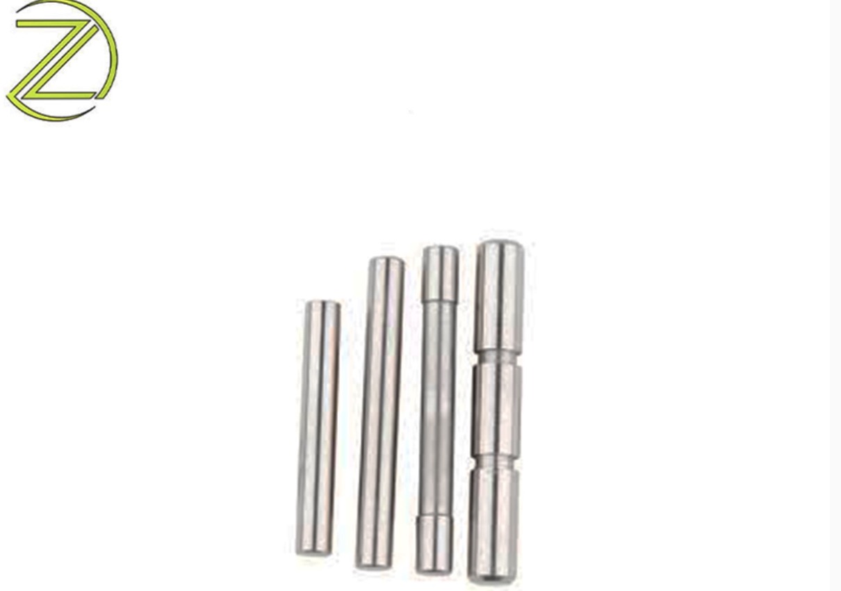
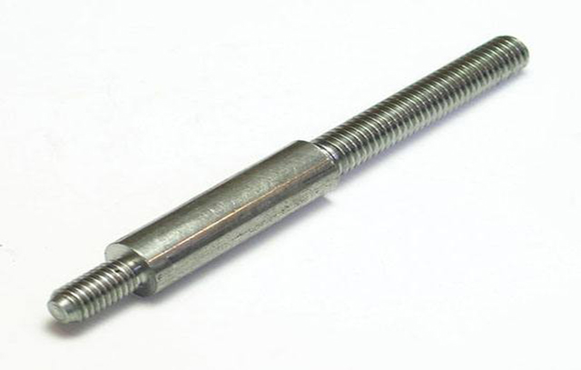
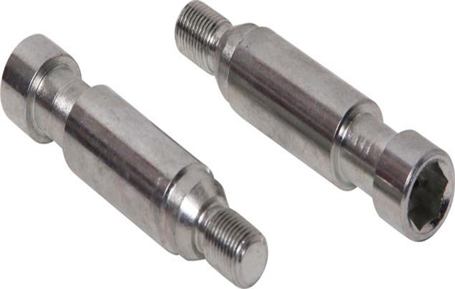
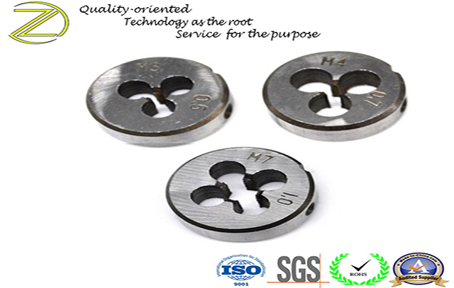
What are dowel pins used for? The dowel pin is mainly used between the screws fastened between the two parts to ensure the accuracy of the position. It is mainly used for assembly positioning, and can also be used as overload shear connection in connection and relaxation level safety devices. The basic form is cylindrical pin and tapered pin. Dowel pins are also called positioning pins. Let's learn the main functions and uses of dowel pins: First dowel pins are divided into cylindrical dowel pins and tapered dowel pins. 1.Cylindrical dowel pins(picture1 and 2) 2. Tapered dowel pins(picture3 and 4) The difference between them is: 1. Different processing. Cylindrical dowel pins can be pre-processed, and tapered dowel pins are usually matched. 2. Cylindrical dowel pins are often suitable for precise positioning (processing first), and tapered dowel pins are often used for frequent disassembly. 3. Cylindrical dowel pins can play a role of anti-shearing, tapered dowel pins are often used for positioning. Cylindrical dowel pins are fixed in the reamed hole with small interference, which can bear a small load. In order to ensure the positioning accuracy and the tightness of the connection, it should not be disassembled frequently. It is mainly used for positioning and also used as a coupling pin and a safety pin. The tapered dowel pin has good self-locking performance, high positioning accuracy, convenient installation, and multiple assembly and disassembly have little influence on the positioning accuracy. It is mainly used for positioning and can also be used as a connecting pin. The pin hole needs to be reamed. Material selection for dowel pins: If the workpiece needs to be clamped repeatedly during use, the fixed pin should have good wear resistance, and a better material should be selected, such as 20#steel or 45#steel, with surface carburizing and quenching. The material can also be selected according to actual usage. Commonly used materials are generally: stainless steel 303/304/316, Q235, 20# steel, 45# steel, brass,ect. Customization is accepted, please feel free to send drawings to inquire at any time, thank you!
-
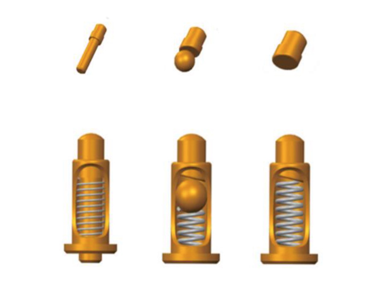
How to solder pogo pins? POGO PIN is a very commonly used electronic connector which consists of a turning needle tube, a turning needle and a compression spring. It keeps the needle in the needle tube and relies on the spring to provide contact force to establish an electrical connection between the needle and the mating parts. I believe many people do not know how the pogo pin is soldered. So let's follow ZLD to understand how the pogo pin is soldered on the PCB board? First of all, let us introduce the pogo pin types to you. There are many types of pogo pins, including upright pogo pins, side pogo pins, double-ended pogo pins, standard pogo pins, etc. Its function is very large, and installation is very important, so what are the installation methods of pogo pins ? Right-angle solder tail: The tail is bent plug-in encapsulation, allowing designers to have more choices in the use of space. Straight solder tail: normal plug-in encapsulation, easy to solder. Surface Mount (SMT): Good stability, the bottom of the needle tube is a flat-bottomed design, can be vertical or horizontal installation, easy to solder with PCB board. Some needle tubes are equipped with positioning pins at the end, which will not cause offset when soldering with PCB board, and the positioning effect is good. Xiamen ZhongLiDa Machinery, as a professional CNC product manufacturer, wholeheartedly provide you with quality products and services.
-
1. The purpose of nonconforming product control Prevent the unintended use or delivery of substandard products. 2. The method of controlling nonconforming product is Recognize first and then control. Control process of unqualified products 1. Identification Identify unqualified: the basis or standard for judging whether the product is qualified or not. -Product Standards —Customer requirements —Process documents -Inspection documents -Template -Explanation and advice from superiors 2. Identification Identification of inspection status —Identifies "pending" or "unqualified". —Production team: unqualified semi-finished products and raw materials should be marked with "to be processed" or "unqualified". —The inspector stamps the inspection stamp in the corresponding item column of the random card, process card or "rework order" as a "unqualified" mark. -Its role is: traceability. —Final inspection: identification of unqualified brand. Or write down (notify) unqualified phenomena, such as (leakage, cracking, few holes, wrong model, serious indentation, few processes, wrong materials, etc.). 3. Isolation Requirements: Clear separation from normal qualified products. —Red plastic tray/material box. —Special independent defective product rack. -Divide the unqualified area and place the defective products in the unqualified area. —The placement of the production area is different from that of other products to show the difference, and then pull it to the repair or rework area as required. —Regularly arrange personnel to the defective product area for confirmation and quantity registration 4. Record -Correctly record the type, batch, inspection date, inspection basis, quantity of non-conforming products, and inspection results of the unqualified products on the prescribed inspection report. —The inspection report is reviewed and approved as required. -Process: 5. Review When the amount is large, or when it has a large impact on the company's reputation and funds, it must be reviewed. (1) Incoming inspection: Disposal opinions signed by the inspection supervisor and above (if necessary, the technical department, production, supply chain, and related departments shall be organized to conduct review). (2) Process inspection: For batches of unqualified products, the Quality Management Department organizes relevant departments and relevant personnel to review. (3) Final inspection: The person in charge of the quality control department approves the disposal conclusion, and when necessary, the technical department participates in the review. 6. Disposal Including the following: selection and use, repair, concession, disposal, corrective and preventive measures. (1) Disposal of unqualified purchases —Return -Concession acceptance —Require the supplier to take relevant corrective and preventive measures -Our factory will arrange personnel to review the factory for many consecutive batches of unqualified suppliers and a large number of severely unqualified supplie...
-
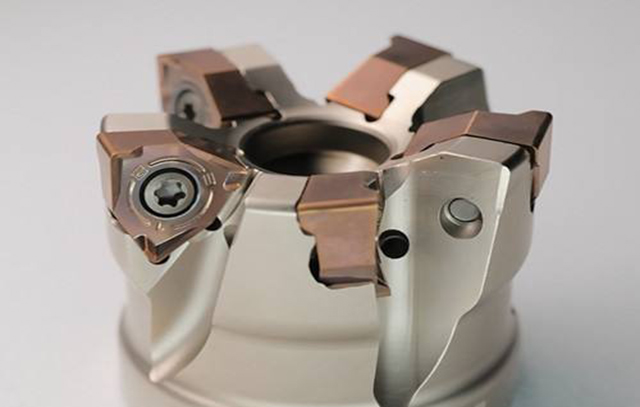
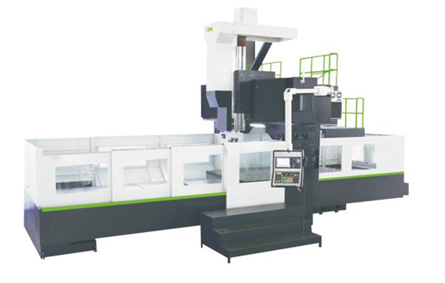
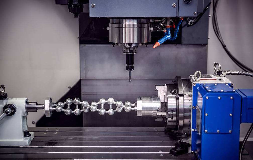
Plunge milling, also known as Z-axis milling, is one of the most effective machining methods for high removal rate metal cutting. For surface machining, grooving and machining with large tool overhangs of difficult-to-machine materials, the processing efficiency of plunge milling is much higher than that of conventional end milling. In fact, when a large amount of metal material needs to be removed quickly, the plunge milling method can reduce the processing time by more than half. ▉advantage In addition, plunge milling has the following advantages: ①It can reduce the deformation of the workpiece; ②It can reduce the radial cutting force acting on the milling machine, which means that the spindle whose shaft system has been worn can still be used for plunge milling without affecting the processing quality of the workpiece; ③The tool overhang is large, This is very beneficial to the milling of the groove or surface of the workpiece; ④It can realize the grooving of high-temperature alloy materials (such as Inconel). Plunge milling is very suitable for rough machining of mold cavities and is recommended for efficient machining of aerospace parts. One of the special applications is plunge milling of turbine blades on a three-axis or four-axis milling machine. This kind of processing usually needs to be performed on a dedicated machine tool. ▉ Working principle When the turbine blade is plunge-milled, it can be milled from the top of the workpiece down to the root of the workpiece. Through simple translation of the X-Y plane, extremely complex surface geometries can be processed. When implementing plunge milling, the cutting edge of the milling cutter is formed by overlapping the profile of each blade, and the plunge milling depth can reach 250mm without vibration or distortion. The cutting motion direction of the tool relative to the workpiece can be either downward or downward. Upward, but generally cutting downward is more common. When plunge milling the inclined plane, the plunge milling cutter makes compound movement along the Z axis and X axis. In some processing occasions, spherical milling cutters, face milling cutters or other milling cutters can also be used to mill grooves, milling surfaces, milling bevels, and milling cavities. ▉ Scope of application The special plunge milling cutter is mainly used for roughing or semi-finishing. It can cut into the concave part of the workpiece or cut along the edge of the workpiece. It can also mill complex geometric shapes, including root cutting. In order to ensure a constant cutting temperature, all shank plunge milling cutters adopt internal cooling. The cutter body and insert design of the plunge milling cutter can cut into the workpiece at the best angle. Usually the cutting edge angle of the plunge milling cutter is 87° or 90°, and the feed rate ranges from 0.08 to 0.25 mm/tooth. The number of inserts clamped on each plunge milling cutter depends on the diameter of the milling cutter. For example, ...
-
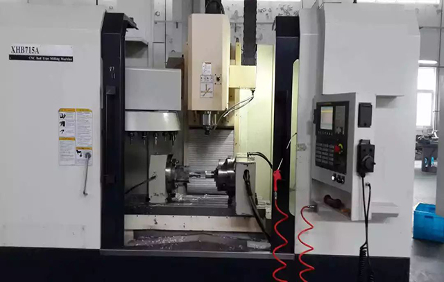
NC (Numerical Control, digital control, referred to as numerical control) refers to the use of discrete digital information to control the operation of machinery and other devices, which can only be programmed by the operator. CNC CNC technology application The development of CNC technology is quite rapid, which greatly improves the productivity of mold processing. Among them, the CPU with faster operation speed is the core of the development of CNC technology. The improvement of CPU is not only the improvement of operation speed, but the speed itself also involves the improvement of CNC technology in other aspects. Because of the great changes in CNC technology in recent years, it is worth a review of the current application of CNC technology in the mold manufacturing industry. Block processing time and others Due to the increase in CPU processing speed, and CNC manufacturers applying high-speed CPUs to highly integrated CNC systems, the performance of CNC has been significantly improved. Faster and more sensitive systems achieve more than just higher program processing speed. In fact, a system that can process part machining programs at a fairly high speed may also behave like a low-speed processing system during operation, because even a fully functional CNC system has some potential problems that may become limitations The bottleneck of processing speed. At present, most mold factories realize that high-speed machining requires more than short processing time. In many ways, this situation is very similar to driving a car. Will the fastest car win the race? Even a spectator who watches the car race occasionally knows that in addition to speed, there are many factors that affect the outcome of the race. First of all, the driver's knowledge of the track is important: he must know where there are sharp turns so that he can slow down appropriately and pass the curve safely and efficiently. In the process of processing molds with high feed speed, the to-be-processed trajectory monitoring technology in CNC can obtain the information of sharp curves in advance. This function plays the same role. Similarly, the driver's sensitivity to other drivers' actions and uncertainties is similar to the number of servo feedbacks in the CNC. Servo feedback in CNC mainly includes position feedback, speed feedback and current feedback. When a driver is driving around the track, the consistency of the movement, whether he can brake and accelerate skillfully, has a very important impact on the driver's performance on the spot. Similarly, the bell-shaped acceleration/deceleration and to-be-processed track monitoring functions of the CNC system use slow acceleration/deceleration instead of abrupt speed changes to ensure smooth acceleration of the machine tool. In addition, there are other similarities between the car and the CNC system. The power of the racing engine is similar to the drive and motor of the...
-
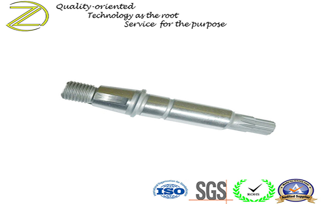
Basic requirements for motor shafts What are the basic requirements for motor shafts? (1) Must have sufficient strength. That is to say, under normal load and specified special conditions (such as sudden short circuit, etc.), any part of the shaft cannot produce residual deformation or damage. (2) Must have sufficient rigidity. That is, the deflection of the rotating shaft must be within the allowable range. (3) There should be sufficient difference between critical speed and working speed to avoid resonance. Xiamen Zhonglida Machinery Processing Co., Ltd. has more than 50 sets of motor shaft manufacturers, such as centering machines, precision CNC lathes, centerless grinding, surface grinding, cylindrical grinding, CNC machining centers, and other first-class equipment. It can process materials such as steel, iron, aluminum, copper and other materials. The processing length can be 2-600MM, the processing diameter can be 2-210MM, and the processing accuracy can be 0.005. It can be milled, drilled, and tapped. Wire, slotting and other processes. The company has a high-level processing system, with advanced equipment and strong technical force, to provide customers with perfect service. Over the years, our company has won wide acclaim from many customers for its strong technical strength, excellent pre-sales, after-sales service and good reputation.
-
Worm gear drive is a drive that changes the direction of the drive. In the process of force transmission, the pressure generated is large, the friction is serious, and the heat generated is also large. In order to avoid gluing, in the selection of materials, softer alloy materials are often used because of the lower speed of the worm gear, while the worm is Use steel materials with greater strength. The number of worm heads can be selected according to the transmission ratio and transmission efficiency requirements. The number of worm heads is small, the transmission ratio is large, but the efficiency is low. To increase efficiency, the number of worm heads should be increased. But the more worm heads, the more difficult the processing. In meeting the transmission requirements, the fewer the number of worm heads, the better. There is usually a device for controlling the rotor behind the head of the electric fan. When pressed, the fan can be turned, and the direction of the fan can be fixed by pulling it out. The lower part that drives the rotating head of the electric fan can be regarded as a crank rocker mechanism. Driven by the worm gear drive, the lower gear rotates with it, and the rocker connected to it can swing within a certain angle under its drive, thereby achieving the purpose of allowing the fan to swing its head back and forth.
-
The purpose of electroplating is to plate a metal coating on the substrate to change the surface properties or size of the substrate. Electroplating can enhance the corrosion resistance of metals, increase hardness, prevent abrasion, improve conductivity, smoothness, heat resistance and beautiful surface. Depending on the purpose of the coating and the electrochemical reaction between the coating and the substrate, the coating can be divided into many types. Coating material ① Classification according to the purpose of the coating The coating usually has two uses, namely: to give or improve the surface condition of the material, or to make the surface structure of the material have a certain function. Therefore, it can be generally divided into decorative, protective coating or functional coating. 1. Protective decorative coating Corrosion, rust, etc. are the greatest threats to product life, which will not only damage the appearance, but also affect the function of the product. In addition to improving the appearance of the product, the general decorative coating can also play a protective role, such as chemical anti-corrosion and anti-rust, or mechanical anti-wear to reduce friction. 2. Functional coating Functional coating mainly refers to those coatings that can make the surface of the material have a special function. Various new functional coatings can increase the surface hardness of the material, improve friction, reduce wear, improve electrical conductivity, reduce contact resistance, enhance magnetism, prevent diffusion and penetration, or repair worn parts. ②. Classification according to the electrochemical relationship between the coating and the substrate According to the electrochemical relationship between the coating and the substrate, the coating can be divided into cathodic coating and anodic coating. The liveliness of the metal is different, which is also an important way to judge the type of coating. 1. Cathodic coating The metal substrate of the cathodic coating is more active than the coating. Such a coating usually covers the substrate completely to protect the substrate. The typical ones are copper plating and nickel plating on steel. Since the cathodic coating only has a certain thickness, it has a protective effect on the substrate. Therefore, the coating thickness and porosity are required. Usually, a coating thickness gauge is used to control the thickness of the coating. 2. Anode coating The plating metal of the anodic coating is more active than the substrate. When the coating encounters corrosive substances, the coating will corrode first, thereby protecting the substrate from corrosion. Typically, there is zinc plating on steel. The above is the plating classification knowledge organized by the editor. If you want to know the coating thickness measurement method and the coating thickness gauge product, please click "How to use the coating thickness gauge to measure the coating thickness" for details.
-
Low speed wire cut, also known as low-speed walking, uses continuous moving thin metal wires (called electrode wires, generally copper wires) as electrodes to perform pulsed spark discharge on the work piece, which generates high temperatures above 6000 degrees, etc. A CNC machining machine that becomes a work piece. The principle of slow wire processing is the phenomenon that there is a gap between the wire electrode and the work piece, and the electrical discharge is continuously removed. Walk slowly. Unlike CNC turning, which is suitable for processing Dowel Pins, Low speed wire cut is more suitable for irregular workpieces that require right-angle cutting. Since the Low speed wire cut machine adopts the method of continuous wire feeding of the wire electrode, that is, the wire electrode completes the processing during the movement, so even if the wire electrode is worn, it can be continuously supplemented, which can improve the processing accuracy of the part. The surface roughness of the work piece processed by the slow-feed wire cutting machine can usually reach Ra = 0.8 μm and above, and the roundness error, straight line error and dimensional error of the slow-feed wire cutting machine are much better than those of the fast-feed wire cutting machine. For high-precision parts, Low speed wire cut machines are widely used. In addition to early small and medium-sized enterprises, it is also very common in processing plants of large enterprises such as aviation, automotive, and medical. WORKING PRINCIPLE Jog wire is a machining machine that uses continuous moving thin metal wires (called electrode wires) as electrodes to perform pulse spark discharge on the work piece to remove metal and cut and form. Loose contact light pressure discharge between the wire electrode and the work piece during slow wire processing. When the flexible electrode wire and the work piece are close to the commonly considered discharge gap (for example, 8 to 10 μm), spark discharge does not occur. Even when the electrode wire has contacted the work piece and the gap is no longer visible from the microscope, it is often not visible. To the spark, a normal spark discharge occurs only when the work piece bends the electrode wire and deviates a certain distance (a few microns to several tens of microns). At this time, for each 1 μm of wire electrode feed, the discharge gap does not decrease by 1 μm, but the electrode wire increases a little tension between the wires, and the work piece increases a little lateral pressure. Obviously, only after maintaining a slight contact pressure between the electrode wire and the work piece In order to form a spark discharge. Based on this, it is believed that there is some kind of electrochemically generated insulating film medium between the electrode wire and the work piece Processing characteristics Surface Quality (1) Nanosecond high peak current pulse power technology In the EDM process, there are two types of metal erosion: meltin...
-
In the processing of parts, those small parts such as bars need to be processed at one time, and those parts need to be processed in batches. In most cases, it will be used. Pogo Pin, Brass Threaded Inserts for Plastic, 316 stainless steel dowel pins, small appliances shafts, brass cable connectors and other round symmetrical products fall into this range, as long as it involves the processing of rod-like parts, as long as the diameter of the processed part is not When the diameter is too large (the diameter cannot be greater than 52mm), the CNC lathe has great advantages in all aspects. If coupled with the matching equipment-feeder (CNC CNC PRECISION AUTOMATIC LATHE), it will generally be used for distribution. Can have a greater advantage), so in terms of this set of equipment, it is a relatively typical small automated production line, whether it is in the speed of processing parts, the molding rate of the product or the cost of the entire production, It has advantages unmatched by other machine tools. The biggest and most important difference between CNC PRECISION AUTOMATIC LATHE and the walking machine is that during the work of the walking machine, the knife moves while the workpiece does not move. CNC PRECISION AUTOMATIC LATHE has long been called a slitting machine in China. It is mainly used for batch processing of small rod-shaped parts. Most feeders pass the bar through the through hole of the spindle, and the collet is automatically clamped. If the parts that need to be processed in the processing process are protruding outward for a certain distance, then the parts need to be equipped with a tip. If the tail needs to be processed, a second spindle is required. If the machined parts need to be machined with four or six drill holes, then a power tool holder and spindle indexing are needed. For CNC PRECISION AUTOMATIC LATHE, the biggest limitation is the limitation of the rod material diameter. At present, the largest type of center lathe can only process parts with a diameter of 50 mm. As long as it is a part that can be machined by CNC PRECISION AUTOMATIC LATHE, its machining accuracy, machining speed, and cutting machine can't match it. There are a lot of CNC PRECISION AUTOMATIC LATHE, but its main advantage is that one time clamping of the part can cut the part up to 200mm in length without stopping the spindle. If you need to process a relatively small part (10mm), both CNC PRECISION AUTOMATIC LATHE and the cutter can be used, but CNC PRECISION AUTOMATIC LATHE can do a lot of this small part without stopping the spindle, but the cutter cannot . The cutting position of CNC PRECISION AUTOMATIC LATHE in the cutting process is always the nearest position where the part is fixed, so the rigidity is very good. The cutter can process more complex and irregular parts. For some flat plate seats that require grooves, the irregular and asymmetric CNC machining part cutter is more suitable than the CNC PRECISION AUTOMATIC LATHE. Zhonglida mach...
-
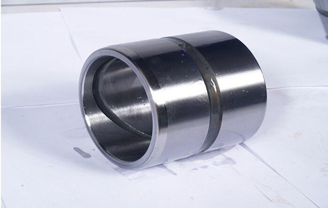
In the moving parts, the parts are worn due to long-term friction. When the clearance between the shaft and the hole wears to a certain extent, the parts must be replaced. Therefore, the designer chooses a lower hardness and better wear resistance when designing. The material is a shaft sleeve or a bushing, which can reduce the wear of the shaft and the seat. When the shaft sleeve or the bushing is worn to a certain extent, it can be replaced. This can save the cost of replacing the shaft or the seat. Generally, the bushing and the seat are used. Interference fit, and clearance fit with the shaft, because wear is unavoidable in any case, can only extend the life, and shaft parts are relatively easy to process; some new designers do not like this design, think that It is an increase in cost during manufacture, but after a period of use, it is still necessary to modify it in accordance with this method. However, the modification is likely to reduce the accuracy of the equipment. The reason is simple. Secondary processing cannot guarantee the position of the center of the seat hole. In addition, the bushing is used to replace rolling bearings (such as camshafts) in places with low speed, high radial load and high clearance requirements (actually, the bushing is also considered as a plain bearing). The material requires low hardness and resistance Grinding, the inner hole of the shaft sleeve can be ground and scraped to achieve high matching accuracy. There must be an oil groove on the inner wall. Lubrication of the shaft sleeve is very important. If dry grinding, the shaft and shaft sleeve will be scrapped quickly. Recommended here Scrap the inner hole wall of the sleeve during installation, which can leave many small pits and enhance lubrication 1. Plain bearing bushing generally function as sliding bearings. In order to save material, the wall thickness of the sleeve is designed according to the axial load required by the bearing. Generally, cast copper and bearing alloy materials are used. The shaft sleeve is divided into open and non-open, which depends on the needs of the structure. Generally, the sleeve cannot bear axial load, or can only bear small axial load. Or add thrust bearings. The shaft is generally round. 2.Bushings generally function as linings. The shaft can be of various shapes, as is the bushing. Bushings can be used to prevent corrosion, eliminate assembly gaps, etc. The shaft sleeve generally plays the role of axial positioning, and the end is in contact with the gear bearing and other parts under compressive stress. Sometimes the shaft must be matched with seals and other standard parts, and it is necessary to ensure that the middle part can pass through the shaft end. The shaft sleeve and seal ring can be made thin to ensure that the parts pass through. Plain bearing bushing have different uses in different occasions, can be axially positioned, can reduce friction and vibration, and can also be used to isolate the shaft from h...
-
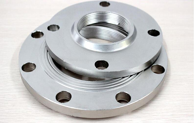
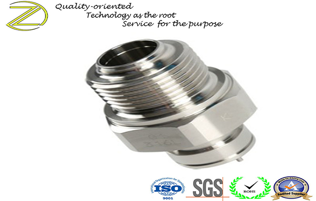
Flange (tool part) Flange (Flange), also known as flange flange or flange. The flange is a part that connects the shaft and the shaft, and is used for the connection between the pipe ends. It is also used in the equipment inlet and outlet for the connection between two devices, such as the reducer flange. The flange connection or flange joint refers to a detachable connection in which a flange, a gasket and a bolt are connected to each other as a group of combined sealing structures. Pipe flange refers to the flange used for piping in pipeline installations, and used on equipment refers to the inlet and outlet flanges of equipment. There are holes in the flange, and the bolts tightly connect the two flanges. The flanges are sealed with gaskets. Flange is divided into threaded connection (thread connection) flange, welding flange and clip flange. The flanges are used in pairs. Wire joint flanges can be used for low pressure pipelines, and welded flanges can be used for pressures above 4 kg. Add a gasket between the two flanges and tighten with bolts. Different pressure flanges have different thicknesses, and they use different bolts. When pumps and valves are connected to pipelines, the parts of these equipment and equipment are also made into corresponding flange shapes, also known as flange connections. Any connection parts that are bolted at the periphery of two planes and closed at the same time are generally referred to as "flange", such as the connection of ventilation ducts, this type of parts can be called "flange parts". However, this connection is only a part of the equipment, such as the connection between the flange and the water pump, it is difficult to call the water pump a "flange-type part". Relatively small ones, such as valves, can be called "flange parts". Reducer flange, used to connect the motor and the reducer, and the connection between the reducer and other equipment. Flange connection is to fix two pipes, pipe fittings or equipment respectively on a flange plate first, and add flange pads between the two flange plates, and fasten them with bolts to complete the connection. . Some pipe fittings and equipment already have flanges, which are also flange connections. Flange connection is an important connection method for pipeline construction. The flange connection is easy to use and can withstand large pressures. In industrial piping, in the home, the diameter of the pipe is small and the pressure is low, and the flange connection is not visible. If in a boiler room or production site, flanged pipes and equipment are everywhere. [1] According to the connection method, the flange connection types can be divided into: plate type flat welding flange, neck flat welding flange, neck welding flange, socket welding flange, thread flange, flange cover, neck welding ring Loose sleeve flange, flat welding ring loose sleeve flange, ring groove surface flange and flange cover, large diameter flat flange, large diameter high neck flange,...
-
Tungsten disulfide powder as lubricant coating Tungsten disulfide powder can be sprayed on the surface of the substrate by dry cold air under 0.8Mpa (120psi) pressure. Spraying can be performed at room temperature and the coating is 0.5 micron thick. Alternatively, the powder is mixed with isopropanol to apply a sticky substance to the substrate. At present, tungsten disulfide coating has been used in many fields, such as automotive parts, racing engine parts, aviation parts, bearings, shafts, deep-sea vehicles, cutting tools, blades, cutting tools, knives, mold release, high-precision bearings, Valve components, pistons, chains, etc. In addition, tungsten disulfide is also used as a colored brush in the carbon industry. It can also be applied to super-hard materials and welding wire materials. Tungsten disulfide can completely replace molybdenum disulfide, with comparable price, better quality and stronger performance. In addition, due to the extremely low friction coefficient (0.03 under dynamic and 0.07 under static) of tungsten disulfide powder, its application field is infinitely broad. Anything is possible if you want to get it.
-
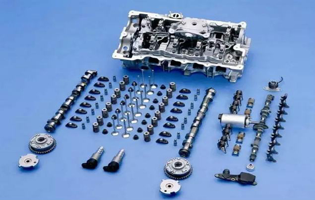
Which products can be processed by CNC machining center 1. Which products can be processed by CNC machining center Machining centers are suitable for complex machining, many procedures, and high requirements, which require the use of various types of ordinary machine tools and many tools, fixtures, and multiple machining and adjustment to complete the parts. The main objects of processing are box parts, complex curved surfaces, shaped parts, disks, sleeves, plate parts and special beads processing. 2. CNC machining center can process box parts Box parts generally refer to parts with more than one hole system, a cavity inside, and a certain proportion in the length, width, and height directions. Such parts are more commonly used in machine tools, automobiles, and aircraft manufacturing. Such parts generally require multi-position hole system and plane processing, with high tolerance requirements, especially strict shape and position tolerance requirements, usually through milling, drilling, expanding, boring, reaming, countersinking, tapping and other processes. There are many tools, it is difficult to process on ordinary machine tools, the number of tooling sets is high, the cost is high, the processing cycle is long, multiple clampings are required, the calibration is correct, and the number of manual measurements is large. The tools must be frequently changed during processing. The important thing is that accuracy is difficult to guarantee. For machining centers that process box-type parts, when there are many machining stations, parts that require multiple rotations of the table can be completed. Generally, horizontal boring and milling machining centers are selected. When there are fewer machining stations and the span is not large. When it is large, you can choose a vertical machining center to process from one end. Complex surface The CNC machining center occupies a particularly important place in the machining industry, especially in the aerospace industry. It is difficult or impossible to complete the complex surface using ordinary machining methods. In China, the traditional method is to use precision casting, and it is conceivable that its accuracy is very low. 3.CNC machining center can process complex curved surface parts Such as: various impellers, wind guide wheels, spherical surfaces, various curved forming dies, propellers and propellers of underwater vehicles, and some other free-form surfaces. These parts can be processed by machining centers. The more typical ones are: a.CNC machining center cam Cams, as the basic components of mechanical information storage and transmission, are widely used in various automatic machines. Such parts have various curved disk cams, cylindrical cams, conical cams, barrel cams, and end cams. Machining this kind of parts can choose three-axis, four-axis linkage or five-axis linkage machining center according to the complicated program of cam. b. Integral impeller of CNC machining center Such parts a...
-
CNC machining Generally CNC machining refers to computer-controlled precision machining, CNC machining lathes, CNC machining milling machines, CNC machining boring and milling machines, etc. Introduction CNC is also called computer gong, CNCCH or CNC machine tool. It is actually a name from Hong Kong. Later it was introduced to the Pearl River Delta in mainland China. It is actually a CNC milling machine. This is a new type of processing technology. The main job is to compile processing programs, that is, to turn the original manual work into computer programming. Of course, you need to have experience in manual processing. Determination of CNC machining routes NC lathe feed processing route refers to the path that the turning tool moves from the tool setting point (or fixed origin of the machine tool) until it returns to that point and ends the machining program, including the path of cutting processing and non-cutting such as cutting in and out Empty travel path. The feed route for finishing is basically performed along the contour of its parts. Therefore, the focus of determining the feed route is to determine the feed route for rough machining and empty stroke. In CNC lathe processing, the determination of processing routes generally follows the following principles. ① The precision and surface roughness of the workpiece to be processed should be guaranteed. ② Make the processing route the shortest, reduce the idle travel time, and improve the processing efficiency. ③ Simplify the workload of numerical calculation and simplify the processing procedures. ④ For some reusable programs, subroutines should be used. CNC pros and cons CNC machining has the following advantages: ① Reduce the number of tooling a lot, and do not need complicated tooling to process parts with complex shapes. If you want to change the shape and size of the part, you only need to modify the part processing program, which is suitable for new product development and modification. ② Stable processing quality, high processing accuracy and high repeat accuracy, adapt to the processing requirements of the aircraft. ③ The production efficiency is higher in the case of multi-variety and small batch production, which can reduce the time for production preparation, machine tool adjustment and process inspection, and reduce the cutting time due to the use of the optimal cutting amount. ④ It can process complex profiles that are difficult to process by conventional methods, and even machining parts that cannot be observed. The disadvantage of NC machining is that the cost of machine tools and equipment is high, requiring a high level of maintenance personnel. CNC machining NC machining refers to machining performed by CNC machining tools. CNC index controlled machine tools are programmed and controlled by CNC machining language, usually G code. The NC machining G code language tells the NC machine tool which Cartesian position coordinates are used, and controls the tool feed speed an...
-
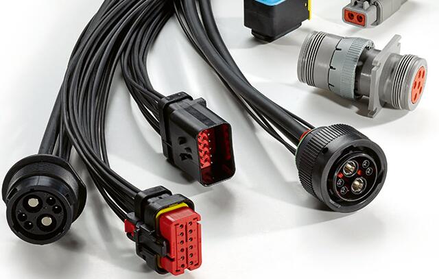
CONNECTORS A connector is a coupling device that joins electrical terminations to create an electrical circuit. Connectors enable contact between wires, cables, printed circuit boards, and electronic components. we attend customer design and manufacture an expansive portfolio of connectors that are engineered to reliably transmit data, power, and signal in the harshest environments, under the most extreme use. Our connectors are manufactured to reduce application size and power usage while enabling increased performance. Our audio and visual connectors offer enhanced board retention and EMI shielding. Our automotive connectors are build to withstand harsh conditions of highway and off-road transportation. Our card edge connectors and sockets support the current SDRAM and DDR memory generations and the new DDR2, DDR3, and DDR4 as well as FBDIMM generations.