CNC machining process of shaft parts
Shaft parts are one of the products we received the most orders. According to the structure of the shaft, it can be divided into three types: optical axis, step axis and special axis. Their role is to support gears, belt wheels and other transmission parts to transmit torque or motion.
The processing technology of stepped shaft is more typical, which reflects most of the content and basic rules of shaft parts processing. The following uses the transmission shaft in the reduction gearbox as an example to introduce the processing technology of a general step shaft, that is CNC machining parts.
1.Part drawing analysis
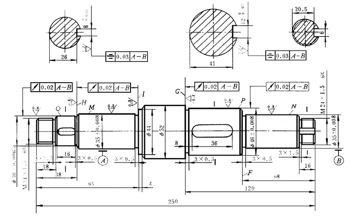
The parts shown in Figure A-1 are the drive shafts in the reducer. It belongs to the step shaft type parts, which is composed of cylindrical surface, shaft shoulder, thread, screw tail retraction groove, grinding wheel overtravel groove and key groove. The shaft shoulder is generally used to install the axial position of the part on the shaft. The role of each ring groove is to make the part have a correct position when assembling, and to make it easy to retract the tool when grinding the outer circle or thread. Install keys to transmit torque; threads are used to install various lock nuts and adjustment nuts.
According to the working performance and conditions, the transmission shaft pattern (Figure A-1) specifies the main journals M, N, the outer circles P, Q and the shoulders G, H, I have higher dimensions, position accuracy and smaller Surface roughness value and heat treatment requirements. These technical requirements must be ensured during processing. Therefore, the key process of this transmission shaft is the machining of journals M, N and outer circles P, Q. For example brass nozzle.
2.Determine the blank
The material of the transmission shaft is 45 steel. Because it belongs to a general transmission shaft, 45 steel can be selected to meet its requirements.
In this example, the transmission shaft belongs to medium and small transmission shafts, and the diameter of each outer circle is not much different, so a 60mm hot-rolled round steel is selected as the blank.
3.Determine the machining method of the main surface
Drive shafts are mostly rotary surfaces, and are mainly formed by turning and cylindrical grinding. Due to the higher tolerance grade (IT6) of the main surfaces of the drive shaft M, N, P, and Q, and the low surface roughness Ra (Ra = 0.8 um), grinding is required after turning. The machining scheme of the outer surface (refer to Table A-3) can be:
Rough turning → semi-finishing turning → grinding.
4.Positioning reference
Reasonably selecting the positioning reference has a decisive effect on the size and position accuracy of the part. Since the several main mating surfaces (Q, P, N, M) and shoulder surfaces (H, G) of the transmission shaft have radial circle runout and end face circle runout requirements for the reference axis AB, it is a solid shaft Therefore, the central hole at both ends should be selected as the benchmark, and the double center clamping method should be adopted to ensure the technical requirements of the part.
The rough reference is the rough outer circle of hot-rolled round steel. The center hole is processed with a three-jaw self-centering chuck for clamping the outer circle of the hot-rolled round steel, the end face of the car, and the center hole are drilled. However, it must be noted that it is generally not possible to drill the center hole at both ends with the blank outer clamp. Instead, use the outer circle of the blank as a rough reference. First machine one end face, drill the center hole, and turn the outer circle at one end. Use the three-claw self-centering chuck for clamping (sometimes put the center frame on the outer circle of the car at the previous step), and drill the center hole on the other end of the car. In this way, the center hole can be processed coaxially.
5.Division stage
For parts with high accuracy requirements, the roughing and finishing should be separated to ensure the quality of the parts.
The processing of the drive shaft is divided into three stages: rough turning (outer circle of rough turning, drilling of center holes, etc.), semi-finishing turning (external circles, steps and repair center holes and minor surfaces of semi-finishing turning, etc.), roughing , Fine grinding (coarse, fine grinding all round). The division of each stage is roughly bounded by heat treatment.
6.Heat treatment process arrangement
The heat treatment of the shaft is determined according to its material and use requirements. For drive shafts, normalizing, quenching and tempering are used more often. This shaft requires quenching and tempering, and is arranged after each outer circle of the rough turning and before each outer circle of the semi-finishing turning.
Based on the above analysis, the process route of the transmission shaft is as follows:
Blanking → Diamond holes on both ends of the car → Drilled outer circle → Quality quenching → Repair center hole → Semi-finished outer circles, grooves, chamfers → Threading thread → Slotted key processing line → Milled key slot → Repair Grinding center hole → grinding → inspection.
7.Processing size and cutting amount
The grinding allowance of the drive shaft can be taken as 0.5mm, and the allowance for semi-finished turning can be selected as 1.5mm. The processing size can be determined by this, see the operation content of the shaft processing technology card.
The selection of the turning amount can be determined by the worker according to the processing situation in the case of single piece or small batch production; generally, it can be selected from the "Machining Process Manual" or "Cutting Amount Manual".
3D printer parts is a Copper pieces, it is different with Shaft machining.
8.Develop the process
The center hole for positioning the fine reference plane should be processed before rough machining, and a process of repairing the center hole should be arranged after tempering and before grinding. The center hole is repaired after quenching to eliminate heat treatment deformation and scale of the center hole. The center hole is repaired before grinding to improve the accuracy of positioning the fine reference plane and reduce the surface roughness of the tapered surface. When formulating the technical process of the drive shaft, while considering the primary surface processing, the secondary surface processing should also be considered. When semi-finishing ¢ 52mm, ¢ 44mm, and M24mm outer circles, you should turn to the size specified in the drawing and process each undercut, chamfer and thread; the three keyways should be milled after semi-finishing It can be processed, so that a more accurate positioning reference can be maintained when milling the keyway, and it can avoid damaging the finished outer surface when milling the keyway after finishing grinding.
When formulating the process, consideration should be given to the arrangement of inspection procedures, inspection items and inspection methods.
Key word: CNC, machining, shaft
32-3# North Two Road, Xinglin, Jimei, Xiamen, 361022 China
Email : sales@xmzldjx.com
Skype : janeliui_01
Tel : +8618650120832
Whatsapp : 13306016335


Scan to wechat: