-

Stainless steel is a remarkable alloy that offers a unique combination of properties, making it a preferred material in a wide range of industries. Its name "stainless" derives from its ability to resist corrosion and staining, even under harsh environmental conditions. Properties of Stainless Steel Corrosion Resistance: The primary characteristic of stainless steel is its corrosion resistance. This is achieved through the addition of chromium to the steel, which forms a thin, invisible, and adhesive oxide film on the surface. This film prevents oxygen and water from reacting with the iron in the steel, thus preventing corrosion. Strength and Durability: Stainless steel is both strong and durable. It can withstand high impact and compression forces, making it suitable for applications that require structural integrity. Easy to Maintain: Stainless steel is easy to clean and maintain. Its smooth surface resists dirt and stains, and it can be cleaned with simple household cleaners or water. Aesthetic Appeal: Stainless steel has a sleek and modern appearance that is visually appealing. It is often used in decorative applications, such as kitchen appliances and fixtures. Heat Resistance: Stainless steel can withstand high temperatures without losing its structural integrity. This makes it suitable for applications that involve heat, such as exhaust systems and furnaces. Applications of Stainless Steel Kitchen Appliances: Stainless steel is a popular choice for kitchen appliances due to its durability, corrosion resistance, and aesthetic appeal. It is commonly used in refrigerators, ovens, dishwashers, and countertops. Architectural Applications: Stainless steel is used extensively in architecture for both interior and exterior applications. It is used in building facades, roofs, railings, and decorative elements. Industrial Equipment: Stainless steel's strength, durability, and corrosion resistance make it ideal for use in industrial equipment. It is used in chemical processing equipment, medical instruments, and oil and gas pipelines. Automotive Industry: Stainless steel is used in various automotive components, including exhaust systems, engine parts, and trim pieces. Its heat resistance and corrosion resistance make it suitable for these applications. Jewelry and Watches: Stainless steel is also used in jewelry and watches due to its durability and aesthetic appeal. It is often used as a base metal for gold and platinum jewelry, and it is a popular choice for watch cases and bracelets. In conclusion, stainless steel's unique combination of properties, including corrosion resistance, strength, durability, and aesthetic appeal, has made it a versatile material with numerous applications across various industries. From kitchen appliances to industrial equipment, stainless steel continues to be a preferred choice for manufacturers and consumers alike.
-
Aluminum is a lightweight yet sturdy metal that boasts a wide range of remarkable properties, making it a versatile material across various industries. Its unique characteristics, such as its low density, high ductility, and excellent corrosion resistance, have contributed significantly to its widespread use. Properties of Aluminum Lightweight: Aluminum has a low density, which is approximately one-third of that of steel. This lightweight nature allows for significant savings in material costs, transportation, and energy consumption. High Ductility: Aluminum can be easily formed and shaped into complex designs and structures. This ductility enables it to be used in a wide range of applications, from automotive parts to building construction. Excellent Corrosion Resistance: Aluminum forms a protective oxide layer on its surface when exposed to air, which provides it with excellent resistance to corrosion. This allows aluminum products to maintain their integrity and appearance for longer periods. Good Conductivity: Aluminum is an excellent conductor of heat and electricity. This property makes it ideal for use in electrical wiring, transformers, and heat exchangers. Non-Magnetic: Aluminum is non-magnetic, which is a desirable property for certain applications such as medical implants, aircraft parts, and magnetic resonance imaging (MRI) equipment. Applications of Aluminum Building and Construction: Aluminum is widely used in building and construction due to its lightweight yet strong nature. It is used in windows, doors, cladding, roofing, and structural components. Aluminum's corrosion resistance also ensures that it maintains its appearance and integrity for years. Automotive Industry: Aluminum is a key material in the automotive industry due to its lightweight properties. Lighter vehicles mean improved fuel efficiency and reduced emissions. Aluminum is used in engine components, chassis, body panels, and other parts. Packaging: Aluminum foil and packaging are ubiquitous in our daily lives. Aluminum's non-toxic, non-corrosive, and lightweight properties make it ideal for food and beverage packaging. Electrical and Electronics: Aluminum's excellent electrical conductivity and lightweight nature make it a popular choice for electrical wiring, transformers, and other electrical components. It is also used in heat exchangers, due to its good heat conductivity. Aerospace: Aluminum's lightweight yet strong properties are crucial in the aerospace industry. It is used in aircraft fuselages, wings, and other structural components. Aluminum alloys are also used in spacecraft and satellites. In conclusion, aluminum's unique properties and versatility have made it an indispensable material across various industries. Its lightweight, ductility, corrosion resistance, and conductivity are just some of the reasons why aluminum remains a highly sought-after metal.
-
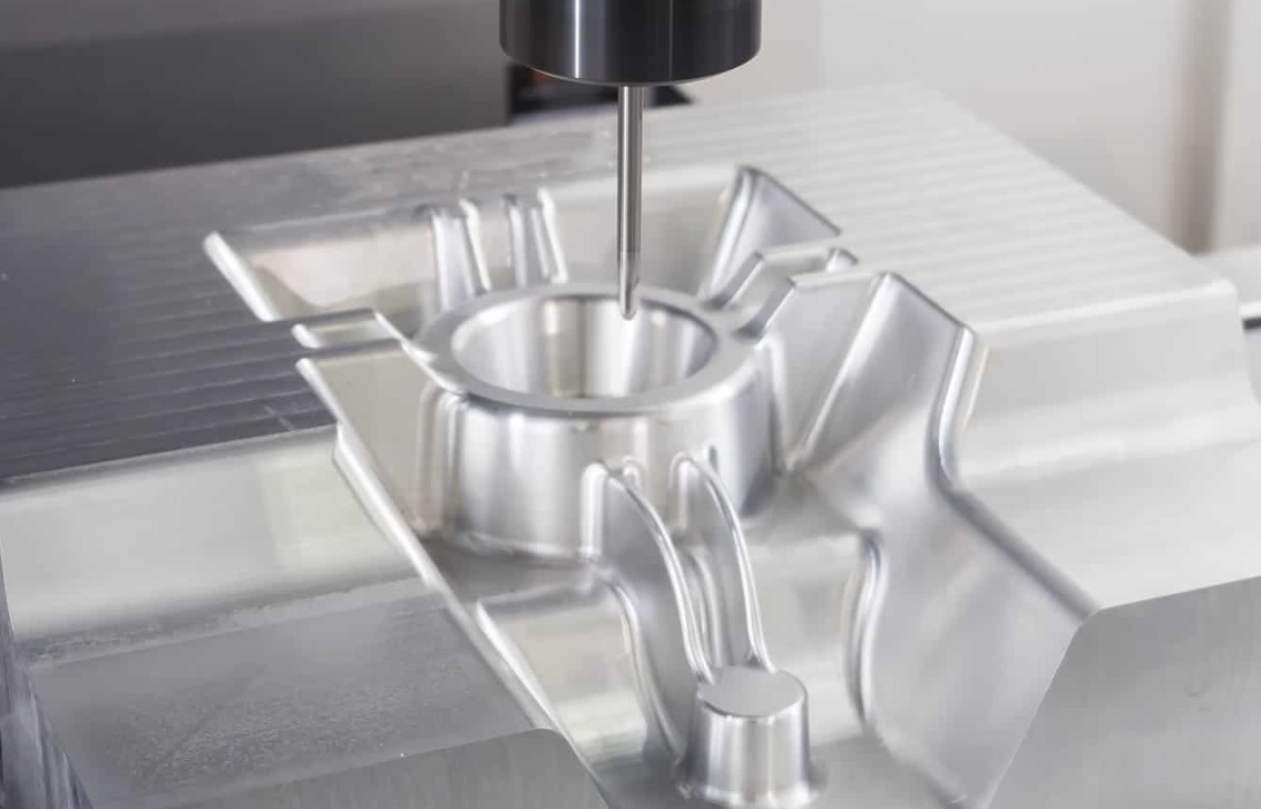
A CNC router, or Computer Numerical Control router, is a precision machining tool that has revolutionized the woodworking, plastics, and metalworking industries. This versatile machine combines the precision of computer-aided design (CAD) software with the physical cutting capabilities of a router to create intricate and accurate parts and products. The primary use of a CNC router is for cutting and shaping various materials. Whether it's wood, plastics, aluminum, or other metals, a CNC router can quickly and precisely cut the material according to the programmed design. The router head, which holds the cutting bit, moves along the three axes (X, Y, and Z) guided by the computer-controlled system. This allows for complex cuts and shapes to be achieved with minimal human intervention. One of the most common applications of a CNC router is in the furniture-making industry. From cabinets and countertops to custom furniture and decorative pieces, CNC routers can cut intricate designs into wood with unmatched precision. The ability to program the router to cut exact dimensions and shapes means that furniture can be produced with tighter tolerances and less waste. CNC routers are also widely used in the sign-making industry. They can cut letters, logos, and designs into a variety of materials, including acrylic, aluminum, and wood. The precision of the cuts allows for crisp, professional-looking signs that are both durable and visually appealing. In addition to cutting, CNC routers can also be used for engraving. By using a specialized bit, the router can carve intricate designs into the surface of a material, creating beautiful and unique patterns. This technique is often used for personalizing items like plaques, awards, and gifts. Moreover, CNC routers are becoming increasingly popular in the prototyping and manufacturing industries. They allow for quick and efficient production of prototypes and parts, reducing the need for expensive and time-consuming manual labor. The precision and repeatability of CNC routers make them ideal for mass production of identical parts. In summary, CNC routers are versatile and powerful tools that have numerous applications across various industries. Whether it's for cutting, shaping, engraving, or prototyping, a CNC router can help you achieve precise and efficient results.
-

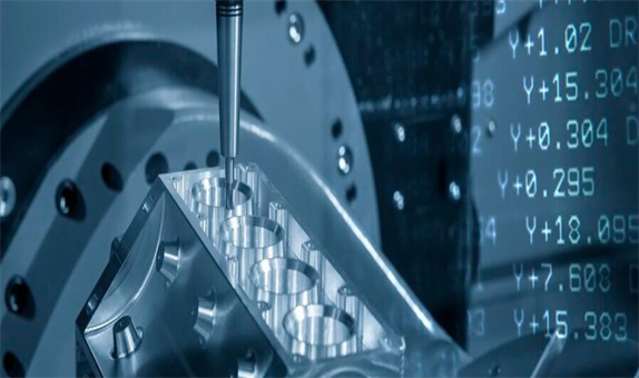
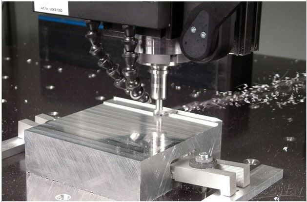
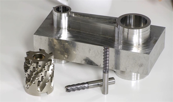
In the world of computer numerical control (CNC) machining, CNC milling and CNC turning are two essential processes that play a crucial role in the manufacture of precision components and parts. While both involve the removal of material from a workpiece to achieve a desired shape, they differ significantly in their approach, application, and the tools used. First and foremost, the fundamental difference lies in their working principles. CNC milling utilizes a rotating cylindrical cutting tool, known as an end mill or a milling cutter, to remove material from the workpiece. The cutting tool can move along various axes to create intricate shapes, grooves, slots, and contours. On the other hand, CNC turning employs a non-rotating cutting tool, typically a lathe tool, which describes a helical tool path on a rotating workpiece. This cutting action is primarily used to create the external surfaces of the workpiece, and when applied to internal surfaces such as holes, it is referred to as boring. The choice of process also depends on the shape and geometry of the workpiece. CNC milling is typically used for machining prismatic parts, where complex shapes and contours need to be created. It excels in creating intricate details and features on the workpiece. Conversely, CNC turning is more suitable for cylindrical or near-cylindrical workpieces, such as shafts, pins, and rods. The rotation of the workpiece allows for efficient and precise machining of these geometries. The tools and cutting methods also differ between CNC milling and CNC turning. CNC milling employs milling cutters that rotate and move along multiple axes, while CNC turning utilizes a stationary cutting tool that moves linearly along the axis of the rotating workpiece. These different approaches allow each process to excel in its respective domain. In terms of accuracy and surface quality, both CNC milling and CNC turning can achieve high levels of precision, depending on the quality of the machine, cutting tools, and process parameters. However, each process has its strengths and limitations, which should be considered based on the specific requirements of the workpiece. The applications of CNC milling and CNC turning also vary. CNC milling is widely used in the manufacturing of molds, dies, fixtures, and components with complex geometries. It is particularly suitable for materials such as metals, plastics, and composites. CNC turning, on the other hand, is commonly used in the production of cylindrical parts, such as shafts, spindles, and rods, in industries like automotive, aerospace, and machinery. In conclusion, CNC milling and CNC turning are two distinct CNC machining processes that differ in their working principles, applications, tools, and cutting methods. The choice between the two depends on the specific requirements of the workpiece, including its shape, geometry, material, and the desired level of precision. Understanding the differences between these processes is crucial ...
-
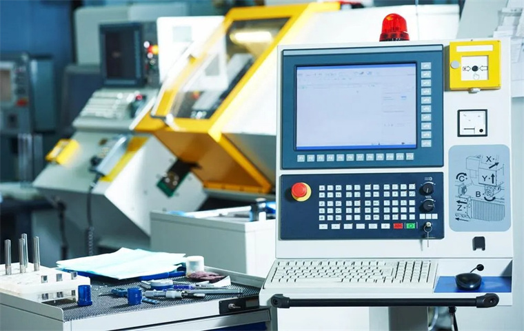
This article will describe the different parts of a CNC machine. Some parts are common between lathes and mills, like the control unit, driving system, and feedback system, while others are specific to a certain type of machine. For example, tailstocks and headstocks are only found on CNC lathes. 1. Input Device The “input device” for a CNC machine is the means by which CNC programs are loaded into the machine. This input device could be the keyboard (to directly input G-code commands), a USB flash drive (to transport a completed program from another computer), or wireless communication (if the program is to be downloaded from another computer using the local network). 2. Machine Control Unit (MCU) The MCU (machine control unit) is the set of electronic hardware and software that reads the G-code supplied by the input device, and translates it into instructions that can be executed by the tool drivers to perform the desired machining actions. It is one of the most important CNC machine components. The MCU interprets the G-code coordinates into movements carried out by servo motors along the various machine axes. It also interprets information from feedback sensors to ensure that the tool is in the expected position after the movement is completed. The MCU also controls tool changers and coolant activation as specified by the G-code.
-
1) Select the right tool and cutting data for the job. Proper tool maintenance is crucial to minimise problem-solving times, particularly in vibrations, poor chip control, and sudden tool breakage. Selecting the appropriate combination of tools and cutting data is essential to reduce the overall tool maintenance needed in the first place. 2) Store your cutting tools appropriately. I have seen machinists spending hours searching for the elusive tool they need to complete that urgent job. And after finding it, they realise it is damaged, hidden behind the CNC machine in the "I'll deal with it later" area. We waste countless hours every year looking for tools for jobs that should only take minutes to produce. Effective tool storage practices are the foundation of maintenance. Whether your workshop is organised or cluttered, neglecting tool care can compromise the efficiency of your machining outcomes. Implementing proper tool storage practices is essential for safeguarding the condition of your tools. 3) Handling your cutting inserts with care. Inserts are fragile, and storing them in your pockets, open containers, or surfaces where they might come into contact with other inserts or elements could cause chipping. The best practice is to store them in their respective boxes supplied when you move them from your inventory to your machine. This ensures they stay protected and in top condition. Safeguarding them in this manner is essential for their long-term performance and durability.
-
CNC machining is the modern replacement of analog devices, in which movement was dictated by turning wheels, levers and cams controlled by a machinist. This earlier process utilized simple scales and patterns that resulted in a lack of uniformity and low precision. In comparison, CNC machines are digitally controlled using numerical coordinates defining their continuous movement. Digital controls ensure that cutting is uniform and repeatable, resulting in consistent high-quality milled parts. Though CNC machines can be used in combination with other technologies, for the purposes of this article, we will focus on CNC use in subtractive manufacturing processes where computerized controls are used with machine tools to remove layers of material from a stock piece. ZLD has been using CNC machines to build plastic injection tooling, silicone molding tooling and fixtures; to fabricate metal components; and to prototype plastic components prior to making production tooling.
-
Steel and iron are both metals, but there are several key differences between them: Composition: Steel is an alloy of iron and carbon, typically containing between 0.2% and 2% carbon. Pure iron has a much lower carbon content and is typically found in the Earth's crust as iron ore. Hardness and strength: Steel is harder and stronger than iron due to the carbon content. The carbon in steel reacts with the iron to form iron carbide, which strengthens the material. Temperature: Iron melts at a higher temperature than steel, requiring more heat to reach its melting point. Applications: Steel is used in a wide range of applications due to its strength, hardness, and corrosion resistance. It is commonly used in construction, automobiles, ships, pipelines, appliances, and many other products. Iron is less commonly used in industrial applications due to its lower strength and hardness, but it is often used in the production of steel and other alloys.
-
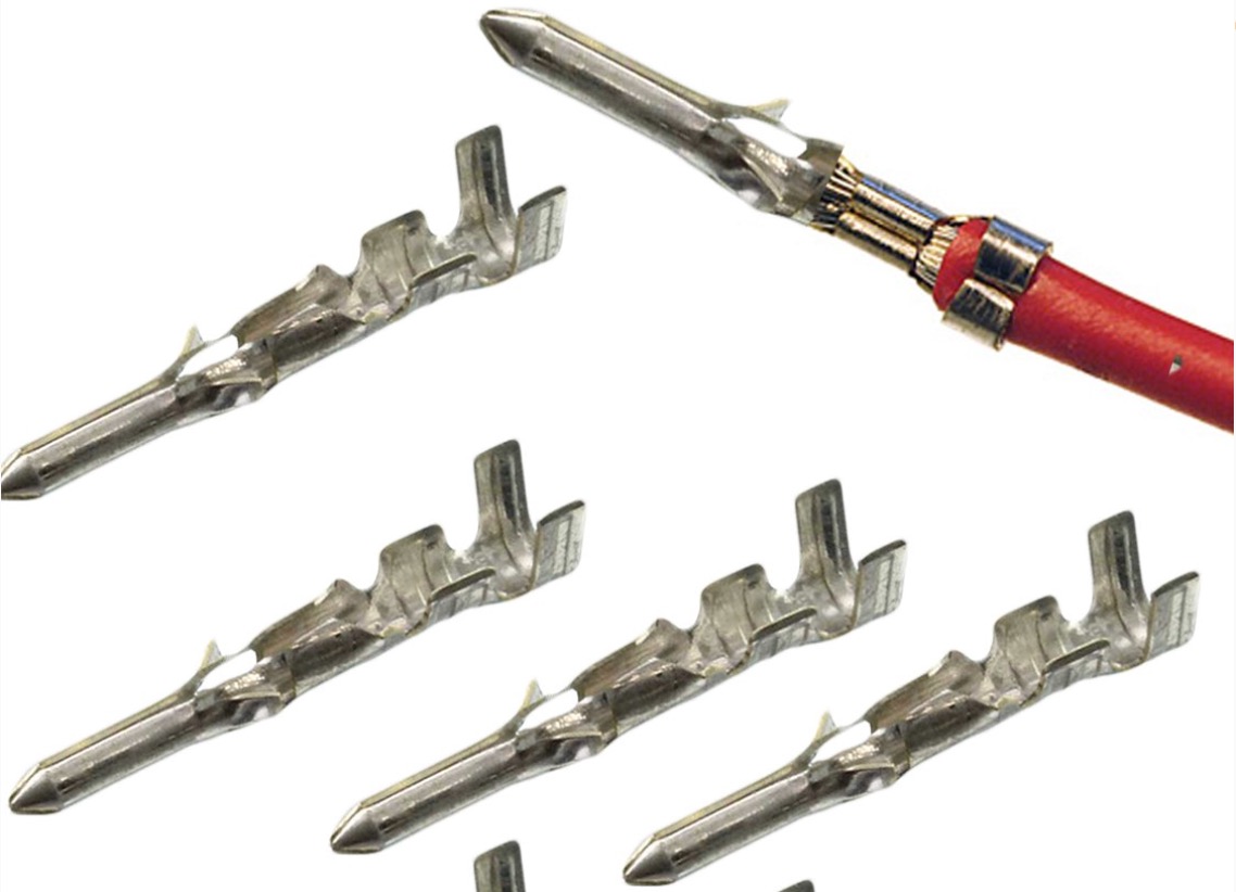
A crimp contact pin is a type of electrical connector that is typically used in the field of electronics and telecommunications. It consists of a metal pin that is crimped onto a wire to create an electrical connection. The crimp contact pin is often used in applications where a secure and reliable connection is required, such as in the assembly of printed circuit boards (PCBs). The crimp contact pin is made of a conductive material, such as copper or brass, and has a flattened or flared end that is crimped around the wire. The crimping process involves using a special tool to compress the pin onto the wire, creating a secure mechanical and electrical connection. The resulting connection provides good conductivity and resistance to vibrations and other mechanical stressors. Crimp contact pins are available in various sizes and shapes to accommodate different wire gauges and applications. They are commonly used in the construction of cables, harnesses, and other wiring assemblies, as well as in the assembly of PCBs. In PCB applications, crimp contact pins are inserted into through-holes or surface-mount pads on the PCB, where they make contact with conductive traces or pads on the opposite side of the board. The use of crimp contact pins offers several advantages over other types of electrical connectors. They provide a secure and reliable connection that is relatively unaffected by vibrations or thermal cycling. Additionally, crimp contact pins are typically less expensive than other types of connectors and are easier to install and remove, making them suitable for use in cost-sensitive and low-volume applications. However, proper installation and handling of crimp contact pins is essential to ensure a reliable connection, and improper crimping can lead to poor connection. Therefore, when installing and using crimp contact pins, correct operating procedures and precautions need to be followed to ensure the reliability and durability of the connection.
-
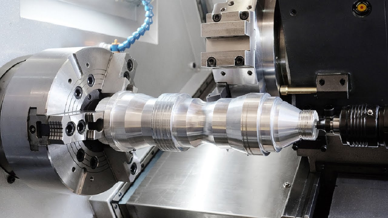
A CNC lathe(CNC turning machine) is a machine that spins material around a central spindle and a fixed cutting tool. Instead of being controlled by physical labor, the movement of your components is determined by coded instructions fed to a computer. A CNC lathe machine is normally used to produce precise round shapes with both an Outer Diameter (OD), and an Inner Diameter (ID). Practically all kinds of structures could be machined with this machine tool, depending on their needs in different industries. All CNC machine tools are automatic, but the usage in the machining industries does not routinely call them by that term. The term "automatic", when it is used at all, still often refers implicitly to cam-operated machines. Thus a 2-axis CNC lathe is not referred to as an "automatic lathe" even if fully automated. CNC machines are more expensive and require a greater initial investment than machines that can be operated manually. However, as this technology becomes the standard, supply is increasing resulting in costs gradually decreasing.
-
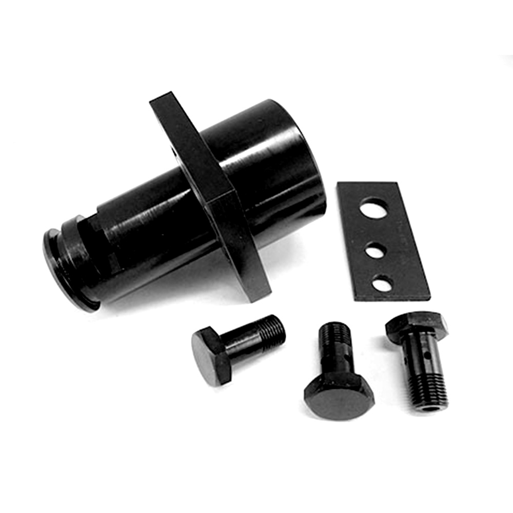
Black oxide is a chemical conversion process used to blacken the surface of a part without adding a thick coating. A chemical conversion process uses a chemical solution to force a reaction on the surface of the part rather than a plating or coating process which adds a thicker layer on top of the base material. Hot black oxide coating consists of a hot bath of nitrates, nitrites, and sodium hydroxide. The interaction between the ferrous material and the bath turns its surface to magnetite. Then, the material is dipped in alkaline cleaner, water, and caustic soda, making it turn black. What is black oxide used for?
-
The full name of CNC is Computer numerical control. Computer numerical control (CNC) is a method for automating control of machine tools through the use of software embedded in a microcomputer attached to the tool. It is commonly used in manufacturing for machining metal and plastic parts. Computer Numerical Control – Taking digitized data, a computer and CAM program is used to control, automate, and monitor the movements of a machine. The machine can be a milling machine, lathe, router, welder, grinder, laser or waterjet cutter, sheet metal stamping machine, robot, or many other types of machines. This type of machining requires fewer machine operators since one skilled operator can run several machines at one time. Since the CNC is so accurate it reduces errors from the manufacturing process and eliminates unnecessary waste.
-
While pin terminals are used both in electrical & electronic systems, they find more use in electronic/communication systems. An electronic system includes different electronic devices that are interconnected. This network of various components/circuits is connected using different interconnects. An interconnect is a physical/logical connection between 2 electronic devices of networks. Interconnects of various types have been developed for varying purposes such as signal transmission, power distribution, and more. Based on termination ends, these interconnect have been classified into three: 1. Board-to-board connectors 2.. Cable/wire-to-cable/wire connectors 3. Cable/wire-to-board connectors Board-to-board connectors: These connectors are mostly used for interconnecting PCBs without a cable. They save space on cables, hence making them suitable for systems with limited space irrespective of parallel & perpendicular configuration. Motherboard and daughterboard arrangements usually employ board-to-board connectors. board-to-noard-connector Cable/wire-to-cable/wire connectors: As its name suggests, it connects two wires or cables. One end is connected to a permanent wire while the other end to a separable interface. There are a lot of varieties of Cable/wire-to-cable/wire connectors in the market each serving different purposes. cable/wire-to-cable/wire connector Cable/wire-to-board connectors: As its name suggests, Cable/wire-to-board connectors connect a wire to a PCB. They are similar to the wire-to-wire connections, especially in the mating interface. cable/wire-to-board connector Terminals give different meanings when used in different disciplines. From an electrical perspective, it simply means a point at which a conductor comes to an end whether it be a component, device, or network. The textbook definition of a terminal would be, a connecting joint at an endpoint, acting as a reusable interface and creating a point where external circuits can be connected. To locate it in a circuit you can look at it at the end of a wire probably fitted with a connector or a fastener.
-
CNC turning is a CNC process where a cutting tool, a typically non-rotating component of the lathe or turning center, removes material from a rotating rigid material. This process produces different shapes and sizes depending on the turning operations used. The first part of CNC turning is “CNC,” which stands for “computer numerical control” and is commonly associated with the automation of machining processes. “Turning” is the machining term for a process where the workpiece is rotated while a single-point cutting tool removes material to match the final part design. Therefore, CNC turning is an industrial machining process controlled by a computer and carried out on equipment capable of turning: a lathe or a turning center. This process can take place with the axis of rotation in the horizontal or vertical orientation. The latter being used primarily for workpieces with a large radius relative to their length.
-
CNC stands for Computer Numerical Control milling. This essentially means that the milling machine is moved and monitored by numerical computer control, rather than by hand. CNC milling is a manufacturing process that uses a cutting tool mounted on a rotating spindle to selectively remove material from a raw substrate to get what we want. The workpiece is rigidly mounted on a table that moves or rotates in different planes, so the tool can work at multiple angles. Complex CNC milling machines can have 5 or more independent axes of motion to create more complex shapes or avoid moving the workpiece to a separate machine.
-
Black oxide or blackening is a conversion coating for ferrous materials, stainless steel, copper and copper based alloys, zinc, powdered metals, and silver solder. It is used to add mild corrosion resistance, for appearance, and to minimize light reflection.To achieve maximal corrosion resistance the black oxide must be impregnated with oil or wax.One of its advantages over other coatings is its minimal buildup. There are many advantages of blackening, mainly: Blackening can be done in large batches (ideal for small parts). There is no significant dimensional impact (the blacking process creates a layer about 1 µm thick). It is far cheaper than similar corrosion protection systems, such as paint and electroplating.