Dec 23, 2019
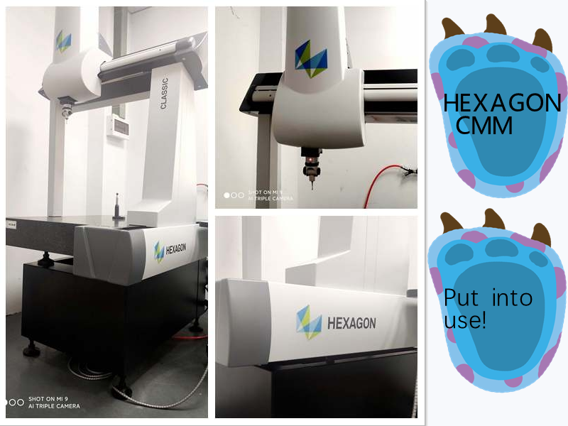
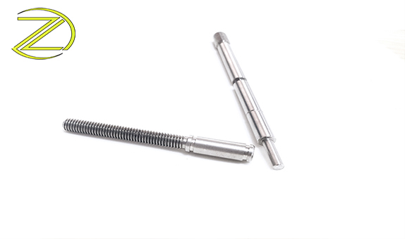
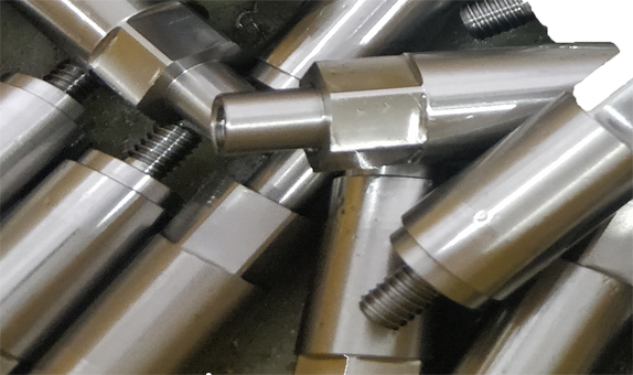
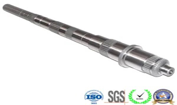
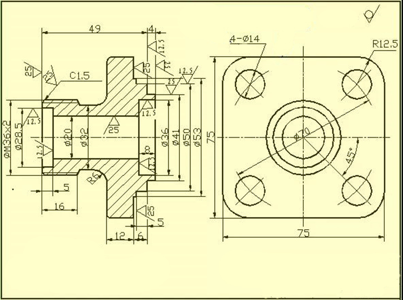
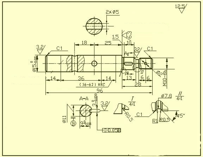
CNC machining process of shaft parts Shaft parts are one of the products we received the most orders. According to the structure of the shaft, it can be divided into three types: optical axis, step axis and special axis. Their role is to support gears, belt wheels and other transmission parts to transmit torque or motion. The processing technology of stepped shaft is more typical, which reflects most of the content and basic rules of shaft parts processing. The following uses the transmission shaft in the reduction gearbox as an example to introduce the processing technology of a general step shaft, that is CNC machining parts. 1.Part drawing analysis The parts shown in Figure A-1 are the drive shafts in the reducer. It belongs to the step shaft type parts, which is composed of cylindrical surface, shaft shoulder, thread, screw tail retraction groove, grinding wheel overtravel groove and key groove. The shaft shoulder is generally used to install the axial position of the part on the shaft. The role of each ring groove is to make the part have a correct position when assembling, and to make it easy to retract the tool when grinding the outer circle or thread. Install keys to transmit torque; threads are used to install various lock nuts and adjustment nuts. According to the working performance and conditions, the transmission shaft pattern (Figure A-1) specifies the main journals M, N, the outer circles P, Q and the shoulders G, H, I have higher dimensions, position accuracy and smaller Surface roughness value and heat treatment requirements. These technical requirements must be ensured during processing. Therefore, the key process of this transmission shaft is the machining of journals M, N and outer circles P, Q. For example brass nozzle. 2.Determine the blank The material of the transmission shaft is 45 steel. Because it belongs to a general transmission shaft, 45 steel can be selected to meet its requirements. In this example, the transmission shaft belongs to medium and small transmission shafts, and the diameter of each outer circle is not much different, so a 60mm hot-rolled round steel is selected as the blank. 3.Determine the machining method of the main surface Drive shafts are mostly rotary surfaces, and are mainly formed by turning and cylindrical grinding. Due to the higher tolerance grade (IT6) of the main surfaces of the drive shaft M, N, P, and Q, and the low surface roughness Ra (Ra = 0.8 um), grinding is required after turning. The machining scheme of the outer surface (refer to Table A-3) can be: Rough turning → semi-finishing turning → grinding. 4.Positioning reference Reasonably selecting the positioning reference has a decisive effect on the size and position accuracy of the part. Since the several main mating surfaces (Q, P, N, M) and shoulder surfaces (H, G) of the transmission shaft have radial circle runout and end face circle runout requirements for the reference axis AB, it is a solid shaft Therefore, the central hole ...
view more